Message boards :
Cafe CPDN :
Off-Grid Solar/Renewable Energy Discussion
Message board moderation
Previous · 1 · 2 · 3 · 4 · 5 · 6 . . . 8 · Next
| Author | Message |
|---|---|
|
Send message Joined: 7 Sep 16 Posts: 259 Credit: 32,091,992 RAC: 22,910 |
People get shocks, eg a kettle lead gets damaged, then they can get a shock from it's live to the earthed washing machine their knee is touching. So they invented earth leakage breakers. Now if neutral and earth were different, no current would flow, no danger. Again, I can't speak to UK wiring practices, but in the US, neutral and ground are supposed to be bonded at the main panel, and only at the main panel. The reason for this is to provide a rapid low resistance path back upstream to trip the overcurrent protection devices. For something like a washing machine, you'll have hot and neutral run to the outlet's corresponding plugs, and then the chassis connected to ground. If neutral breaks, there's nowhere for current to flow, so it simply stops working and the "hot" internal bits are energized, but you don't shock yourself. If the hot wire insulation fails and it bridges to the chassis, then the return path through the grounding conductor will allow enough current to flow to trip the upstream breaker, de-energizing the whole circuit. The intent is that things be wired so you can't have a "low leakage" sort of fault - either things are working properly, fail without shocking people, or trip the nearest upstream overcurrent protection device promptly. And it seems to work well enough in practice, as long as nobody's done something creative like use ground as neutral... That makes no sense at all. Firstly, why aren't they designed to only go one way with some kind of physical change on the top or bottom? I have no idea, I didn't design the damned things. I'm just telling you how they are in the US. Our meter bases typically look like this: https://www.homedepot.com/p/Eaton-200-Amp-Ringless-OH-UG-Single-Meter-Socket-UTRS213BE/202959693 One side is L1, one side is L2, and neutral is run through in the middle. Secondly, the meter reader is going to see your meter being the wrong way up! We haven't had "in person meter readers" in... I've no idea how long. The meters just broadcast data upstream every so often (out here, there's hourly date, transmitted... oh, a few times a day, maybe? You can hear the meter transmitting, it makes a bit of racket while it's doing it). There's a thing called solar islanding. Let's say the power coming into my village dies. Lots of us have solar, we all feed into the grid. The solar is enough to power what everyone's using. Sounds like a good thing to me - we all still have power, including the ones without panels. That doesn't work at all without a decent sized battery system to buffer the changes. Most grid tie inverters won't curtail very effectively for that sort of environment, you'll push voltage out of spec, and they'll shut down. Your dream is technically possible, but it's very much not as anything is implemented that I'm aware of, short of very deliberate microgrids that cost what you'd expect. They're not 7 times worse than Lithium, so it's not worth paying 7 times as much for Lithium. I'd only use Lithium if I really needed it lightweight or small. You just won't let go of your "7, for all people, in all countries, at all times, in all cases" value you came up with, will you? It depends on what you're comparing, for what purposes, in what countries, etc. But they have a predictable life. And you can see them beginning to fail by watching the battery meter. I've got a nice high end shunt and datalogging system in place. What, exactly, should I be looking for to predict lead acid EOL with some decent resolution? Water use is up, and that's good enough for me to think about replacing them. In any case, I look forward to having a LFP bank in my office's enclosure, as it will make my winters an awful lot easier than working with cold lead acid. I'm all for lead acid where it makes sense, it's made sense for a while, but the cost delta and capacity-in-winter delta have changed around enough that LFP is what I'm going with next. And it's not 7x the cost for the same capacity, at least with what I use. Genuine ones seem to be £145 for 250W. So your friend has 4 grand of panels, bloody hell. ... yeah? I've got $8k of panels for my house array, plus the whole rest of the system. Plus what's on my office. $0.50/W is a pretty decent price for UL listed house panels, though you can do better if you're willing to split out an order of a hundred or so with some friends. |
|
Send message Joined: 5 Jun 09 Posts: 80 Credit: 3,046,017 RAC: 3,192 |
That's a superb demonstration of the (in)accuracy deployed by advertisers..... It's actually a 100W panel, but the advertiser has very cleverly played with words and not thought things through properly. Headline figure: 100 200w ...///... Now read the spec, carefully and you find the real maximum output of one of these panels: Maximum power voltage(Vmp) 16V Do a quick bit of very simple arithmetic: Maximum power = max power voltage x max power current putting the provided figures in we get: Max power = 16 x 6.25, which is 100w. So there you have the maximum power, put this through a MPPT (or even a half decent PWM) controller and you will only ever get a maximum power of 100W, no matter what the controller output voltage is Indeed the output from the controller will be slightly lower than this, but (hopefully) the loss is only a couple of watts. So, don't believe the headline figures, but always do a bit of reading and apply a bit of common sense. (And by the way the UK price has dropped to £23.25 for a single panel, with free P&P from China.) |
|
Send message Joined: 9 Oct 20 Posts: 690 Credit: 4,391,754 RAC: 6,918 |
Again, I can't speak to UK wiring practices, but in the US, neutral and ground are supposed to be bonded at the main panel, and only at the main panel. The reason for this is to provide a rapid low resistance path back upstream to trip the overcurrent protection devices.But there would be no need to trip when live touched the chassis, if neutral and ground were not bonded. You still couldn't get a shock. It would be intrinsically much safer because you'd have to manage to touch a faulty live and a faulty neutral at the same time. It's what they do on building sites with those portable isolating transformers (bright yellow in the UK): https://www.s-tools.co.uk/product/isolating-transformer-3-0kva/ I have no idea, I didn't design the damned things. I'm just telling you how they are in the US.Home depot are weird, I had to use a VPN in the USA to connect to their website. Have I just looked at a state secret or something? Why go to the bother of hiding their stuff from foreigners? One side is L1, one side is L2, and neutral is run through in the middle.So the user can simply pull out the meter and shove their hand in there and get 240V? Lovely. Not to mention the turning upside down and altering them in private inside the house. I see no reason to make them removeable, are they unreliable and often need replacing? Ours are just screwed onto the wall, and the 4 wires attached (L/N in, L/N out, we don't have two lives). Mind you, ours are inside a meter box, I gather yours are actually outside! Why aren't they harmed by weather? Here's yours outside, and mine inside:  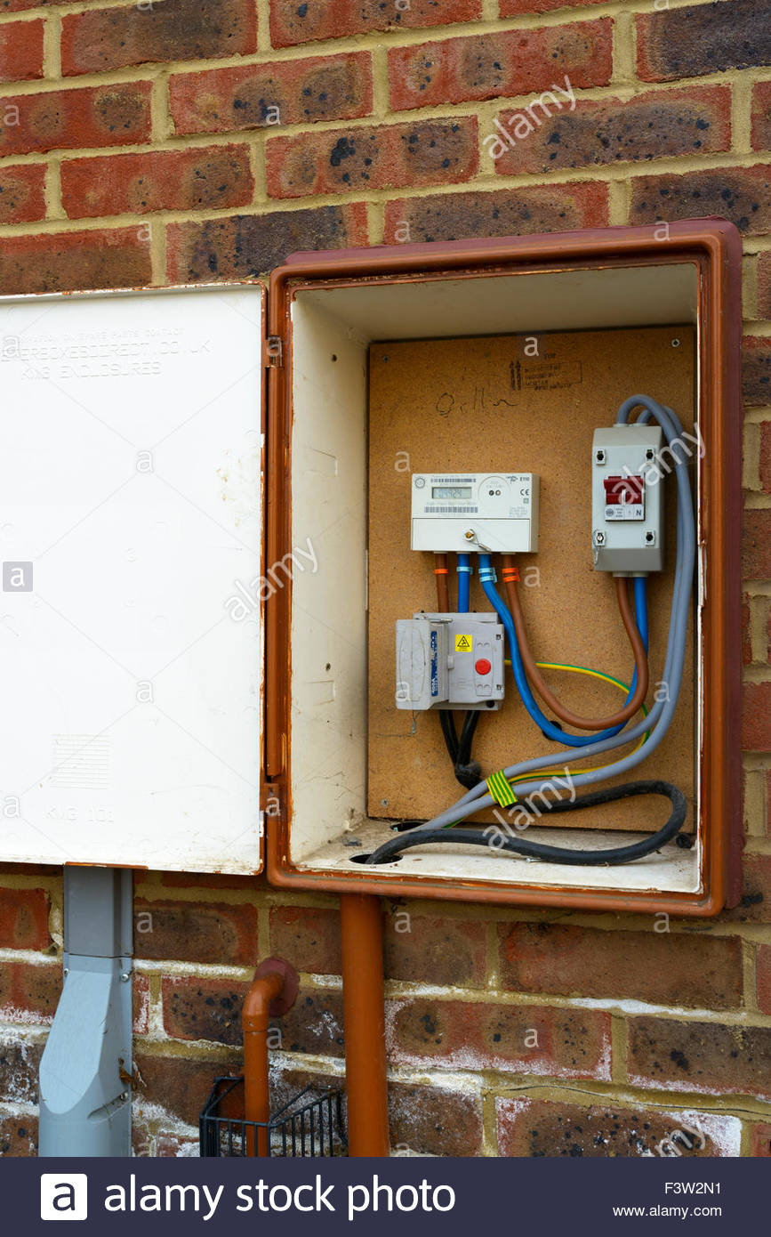 The only reason I can see for neutral going through the meter is so the meter can draw a bit of power if it's electronic. Not sure why the old ones did that, apart from the off peak timer functions we had for cheap power for nighttime storage heaters, but those timers tended to be seperate. We haven't had "in person meter readers" in... I've no idea how long. The meters just broadcast data upstream every so often (out here, there's hourly date, transmitted... oh, a few times a day, maybe? You can hear the meter transmitting, it makes a bit of racket while it's doing it).Why on earth would they make a noise transmitting? It's sent (here anyway) using the mobile phone network, and phones don't make a transmitting noise, it's a few GHz, a bit out of your hearing range. Are yours printing off a bill and posting it or something?! I assume those weird socketed meters were there back when they were mechanical, so you had meter readers then, and they would notice upside down meters. But perhaps they arrived on a predictable schedule so the consumer could make sure it was upright when they appeared. They should have just randomised their visits. I found a youtube video of someone in the USA complaining he'd been cautioned by the electric company because he'd placed a magnet on top of the meter cabinet (not even right on the meter). Assuming he was telling the truth, it was a magnet he used for his work recycling metals to tell which was steel and aluminium. The meter box was a handy place to put it. He proved it had no effect on the meter, but the company thought he was fiddling the meter. We've only just been handed out the transmitting ones, and they weren't compulsory, most people didn't take them because they can spy on you by knowing exactly when you're at home using power, and also because the first batch were (ironically) over-reading LED lights due to the way those lights draw power in short bursts. There's also the worry they can be used to shut people off remotely when there's a lack of power, although that's utter bollocks because they just turn off the power to the whole area instead of telling every individual meter. That doesn't work at all without a decent sized battery system to buffer the changes. Most grid tie inverters won't curtail very effectively for that sort of environment, you'll push voltage out of spec, and they'll shut down. Your dream is technically possible, but it's very much not as anything is implemented that I'm aware of, short of very deliberate microgrids that cost what you'd expect.There's no reason it wouldn't work. Why would the voltage go out of spec? They will attempt to generate 240V, if the load goes up and down, they will adjust. Or are they very basic electronics which assume the grid can take whatever they give, and therefore aren't designed to throttle? I'm assuming for off-grid you can buy tied invertors (to tie to each other?) - I'm thinking of having one small very efficient low power but low quiescent current invertor on all the time, then getting larger ones to switch on when the load is sensed as being heavy (I'd make the sensing circuit myself). So can you get off-grid invertors where you can parallel the outputs? If not, I guess my circuit could always switch the little one off when it switches the big one on. You just won't let go of your "7, for all people, in all countries, at all times, in all cases" value you came up with, will you? It depends on what you're comparing, for what purposes, in what countries, etc.Don't know why you said purpose. The point is I didn't realise they were made in different countries so the lead in particular is astronomically expensive in countries which don't make it, due to shipping. They seem to get made in the UK, so we enjoy very cheap lead batteries. Not sure why the Lithium is so expensive here in shops, when I can ship if from China for a lot less. I've got a nice high end shunt and datalogging system in place. What, exactly, should I be looking for to predict lead acid EOL with some decent resolution? Water use is up, and that's good enough for me to think about replacing them.As they get older, their Ah reduces. Manually, you'd see the voltage getting lower than it used to with the same load. Automatically, I had a very simple battery monitor people buy for their batteries on a yacht, caravan, etc. It estimated the Ah of the battery itself as you used it, it watched the voltage and current as time went on. In any case, I look forward to having a LFP bank in my office's enclosure, as it will make my winters an awful lot easier than working with cold lead acid. I'm all for lead acid where it makes sense, it's made sense for a while, but the cost delta and capacity-in-winter delta have changed around enough that LFP is what I'm going with next. And it's not 7x the cost for the same capacity, at least with what I use.Well if the one I linked to on Aliexpress does what it says on the tin, it's 2x the price, so I'll be using those. I'll buy one and test it thoroughly. Why did you say water use? I though Leads you topped up went out in the 70s? They're all "maintainence free" now. Actually I guess you get three times the depth of discharge without wearing them out quickly, and five times the life out of them, so they're actually worth 15 times as much, although you have to pay the x7 upfront. ... yeah? I've got $8k of panels for my house array, plus the whole rest of the system. Plus what's on my office. $0.50/W is a pretty decent price for UL listed house panels, though you can do better if you're willing to split out an order of a hundred or so with some friends.That's a lot of money to spend on solar. Yes you get it back fairly soon, but it's an astronomical outlay. Mind you some people seem to come up with cash bigger than that to buy a new car. I bought my last car for £500 and it's lasted me 5 years so far. I could never produce 8 grand at once, it's just not possible. |
|
Send message Joined: 9 Oct 20 Posts: 690 Credit: 4,391,754 RAC: 6,918 |
That's a superb demonstration of the (in)accuracy deployed by advertisers.....This is an example of what I was looking at. Nowhere does it say 100W. It states the correct voltage and current, but the watts are a lie all over the listing. https://www.ebay.co.uk/itm/354861602597 He's been reported, as have 3 others. Mind you, since they're about a foot by 2 feet, that's 4.8 times smaller than a genuine 250W panel, which would mean assuming the same efficiency, they could only output just over 50W. So a double lie. (And by the way the UK price has dropped to £23.25 for a single panel, with free P&P from China.)To what panel are you referring, a real 250W one? |
|
Send message Joined: 7 Sep 16 Posts: 259 Credit: 32,091,992 RAC: 22,910 |
But there would be no need to trip when live touched the chassis, if neutral and ground were not bonded. You still couldn't get a shock. It would be intrinsically much safer because you'd have to manage to touch a faulty live and a faulty neutral at the same time. Would you like to re-litigate the entire history of the electrical industry? Because I don't, and I don't see a huge point in it. Yes. If you're 100% insulated from everything, then a random 240VAC line to you doesn't matter, but in reality, that's (I assume...) killed a variety of people. I assume that the NEC isn't just based on the random whims of evilly evil people, twirling their evil mustaches to evilly bond ground and neutral at the panel. There's a range of things to consider, including fault currents, overcurrent protection trip speed, etc. Home depot are weird, I had to use a VPN in the USA to connect to their website. Have I just looked at a state secret or something? Why go to the bother of hiding their stuff from foreigners? Sorry, also a company I don't work for, and have no idea why they do that sort of thing. I don't represent the entire American tech ecosystem. So the user can simply pull out the meter and shove their hand in there and get 240V? It's held in by a retaining ring that also has a power company "Do not remove" tamper evident sort of tag. You can't casually remove it, but nothing technically prevents you from removing the tamper evident connector, pulling it out, etc. I've no particular idea as to what happens when you do that, as I've had no interest in doing so. Typically, they're outside, and they're quite weatherproof. So it doesn't seem to bother them in the slightest. Why on earth would they make a noise transmitting? It's sent (here anyway) using the mobile phone network, and phones don't make a transmitting noise, it's a few GHz, a bit out of your hearing range. Are yours printing off a bill and posting it or something?! If I understand the local tech properly, they short a ~1ohm resistor across L1/L2 at some point in the lower amplitude part of the waveform repeatedly to put some disturbances on the line. It's audible at the meter and nearby wiring, and is definitely not cell modem based. We've only just been handed out the transmitting ones, and they weren't compulsory, most people didn't take them because they can spy on you by knowing exactly when you're at home using power, and also because the first batch were (ironically) over-reading LED lights due to the way those lights draw power in short bursts. What's wrong with over-reading LEDs if their power factor is, as is typical, "trash"? AC meters since times eternal have monitored VA, not watts, and large power consumers will pay a lot of money to get their power factor closer to unity (VA == W). But to measure a random recent-ish LED bulb I have laying around, my Kill-a-Watt says the power factor is an atrocious 0.6 - so it pulls 9.5W, but 15.5VA. I'll just quietly suggest you go understand the difference before railing about yet another thing you find absurd. There's no reason it wouldn't work. Why would the voltage go out of spec? They will attempt to generate 240V, if the load goes up and down, they will adjust. Or are they very basic electronics which assume the grid can take whatever they give, and therefore aren't designed to throttle? Are you talking about any specific model number of inverter with this capability, or are you talking about what you think they ought to be able to do? First, voltage spec is pretty wide. I believe North American spec is 240V +/- 5%, so 228-252V is "in spec." And no grid tie inverter I'm aware of tries to maintain 240V - they simply export what they can, as long as voltage is within spec at the inverter terminals. If you've got a very long AC run to your transformer, you may need to oversize the conductors, or you'll trip the inverters off from voltage rise on the line. Right now, in the evening, I'm 245V at the inverters. I'll typically see 246-247 mid-day, and I've occasionally seen them curtail output. Off grid inverters will do what you claim, but they're generally not happy about being grid tied, as the topology and control systems are rather different, and if, say, the inverter seeks 240V and the grid is 245V, they'll sink power and nasty things happen. The grid is, far as most off-grid inverters are concerned, quite infinite in source and sink ability. I'm assuming for off-grid you can buy tied invertors (to tie to each other?) - I'm thinking of having one small very efficient low power but low quiescent current invertor on all the time, then getting larger ones to switch on when the load is sensed as being heavy (I'd make the sensing circuit myself). So can you get off-grid invertors where you can parallel the outputs? If not, I guess my circuit could always switch the little one off when it switches the big one on. It's possible, though fairly rare. The Outback Radians will stage on in 4kW blocks, but I'm not aware of any that will do a 200W inverter staged with a 2000W inverter or such. There are some designed for paralleling the output that might be able to support staging on and off, but I've not looked into it recently. Manually, you'd see the voltage getting lower than it used to with the same load. Sure, and that's also variant with temperature, water level in the battery, recent charge/load behavior, etc. It's a tolerable way to know if the bank is dead, but voltage on lead acid doesn't get you nearly as much as you'd think. Automatically, I had a very simple battery monitor people buy for their batteries on a yacht, caravan, etc. It estimated the Ah of the battery itself as you used it, it watched the voltage and current as time went on. Did you ever actually validate it? I've seen those, and I've seen those generate some quite absurd numbers. Why did you say water use? I though Leads you topped up went out in the 70s? They're all "maintainence free" now. Deep cycle off grid lead with a 10+ year service life is mostly still flooded. You can get AGMs, but they're about twice the cost per kWh stored, as they cost more up front, and have a shorter service life. However, they also source a lot more amps for a given pack size. Flooded really doesn't like getting past about C/8 or so before it sags. That's a lot of money to spend on solar. The total install was north of $20k, by the time I did the ground mounts, wiring, inverters, etc. It's not cheap in the US. Nor can you just build it as you go. Save your pennies for a while. On the other hand, if you want $4/W costs, there are no shortage of companies willing to get you a loan for it. I just can't wrap my head around that when you can DIY the work for $1-$1.50/W. |
 Dave Jackson Dave JacksonSend message Joined: 15 May 09 Posts: 4353 Credit: 16,598,247 RAC: 6,156 |
There's no reason it wouldn't work. Why would the voltage go out of spec?The problem is more the frequency. Lots of inverters all trying to lock onto each other's frequencies. and none of them stable. They are designed to lock onto a stable grid frequency. It is a bit like flying trapeze. The flyer puts their hands out to be caught and the catcher can then find them. If the flyer is waving their hands about trying to match where the catcher's hands will be it doesn't work. I had to use a VPN in the USA to connect to their website.Quite a lot of companies who only sell to a domestic market do it to reduce the bandwidth they need. How much difference it makes, I don't know but that is the logic with some at least. |
|
Send message Joined: 5 Jun 09 Posts: 80 Credit: 3,046,017 RAC: 3,192 |
Ah, so you've had to change the panel you are talking about (AliRobers have taken down the first panel you linked to). The item in the headline picture makes an interesting claim: 10-30 amps 250W and shows an array of rigid, metal framed, panels, not the flexible, without frames, ones described in the rest of the lies. Yet again the advertiser over-states the performance - read the spec on that so called "250 watt" panel: In the "Item specifics" section: Maximum supply voltage 18V Working current: 5.78A This gives an output of 104.04 watts and in the "product description" section: Current Rating 2.6-5.78 A Voltage 12 V Now the output power has dropped to 69.36 w (which may be more realistic for the panel size) . But they claim 250w!!!! An outright lie. Again, it is impossible for a single panel of the type you linked to supply 250W. (It s worth noting that the controller is rated for ~430W, or is it 396W - they really don't know which is correct) Lesson: 1 - Read the full item description, not just the headline figures. 2 - Do some simple sanity checks on the rating/performance 3 - Don't waste money on these items if they fail either 1) or 2) |
|
Send message Joined: 9 Oct 20 Posts: 690 Credit: 4,391,754 RAC: 6,918 |
The problem is more the frequency. Lots of inverters all trying to lock onto each other's frequencies. and none of them stable. They are designed to lock onto a stable grid frequency. It is a bit like flying trapeze. The flyer puts their hands out to be caught and the catcher can then find them. If the flyer is waving their hands about trying to match where the catcher's hands will be it doesn't work.AC is such a pest, far too much nonsense to consider like frequency and inductance and mains hum and so forth, it would be great if we all changed to DC. So if I were to buy three off-grid invertors which can run in parallel, how do they stay in synch? Do I have to set one as a master? And what happens if there's a lot of invertors on the grid? Won't they pollute the frequency they're trying to set? Imagine a fictitious extreme where we have one normal power station, and 1 million homes with grid tied invertors. How do they keep to the frequency the power station is setting? Quite a lot of companies who only sell to a domestic market do it to reduce the bandwidth they need. How much difference it makes, I don't know but that is the logic with some at least.Just how many people are connecting outside their own market anyway? Just the odd one like in this case where they've been used as an example in a conversation. |
|
Send message Joined: 9 Oct 20 Posts: 690 Credit: 4,391,754 RAC: 6,918 |
Ah, so you've had to change the panel you are talking about (AliRobers have taken down the first panel you linked to).It's Ebay I'm finding the dodgy panels on (AliExpress is more reputable). And I didn't change it, I didn't know I'd linked to one in the first place. The only link I remember making was a battery on AliExpress. Yet again the advertiser over-states the performance - read the spec on that so called "250 watt" panel:No, it's just wrong. No panel is 12V. They vary with the brightness of the sun. Lesson:I'm sick of having to. Every single time I come across nonsense, they're getting reported. |
|
Dave Jackson Send message Joined: 15 May 09 Posts: 4353 Credit: 16,598,247 RAC: 6,156 |
Do I have to set one as a master?Yes. Not all are capable of this so one may need to be more expensive than the others. With regards to the ac/dc argument, the problem is that solid state inverters that can change voltages without lossy transformers didn't appear till long after the decision to go down the AC route was made. Transmission losses are greatly reduced with DC transmission and I suspect that were we designing a system from scratch today we might well choose DC. You can read a history of the arguments in the early days here |
|
Send message Joined: 5 Jun 09 Posts: 80 Credit: 3,046,017 RAC: 3,192 |
Many multi-inverter systems do require a master to prevent (or at worst minimise) all the inverters around looking for the "right" frequency. Looking at the spec for the OutBack Radian inverters suggests they do have a master inverter and a number of "slaves" - everyone of which should synchronise to that one. So no "frequency pollution" (that's a great description of what happens when AC power supplies don't synchronise properly) within the local grid (your shack),or to the big, outside grid. The how part is quite interesting. It really depends on a couple of design decisions. There are two considerations, first is the grid frequency, this is quite easy to establish, the second is phase difference which can be fun - a grid tied inverter will generally be slightly in advance of mains (fraction of a degree). These can both be done in hardware or software or combinations thereof - the inverter designer will have made the choice some time ago. The question about lots of inverters (in different locations and of different types) is one that has been asked quite a few times over the years. The answer is actually quite simple - scale. The main supply to the grid (the big generators) are so much larger than all the inverters so, in terms of frequency, are insignificant. (but who knows in the future when there are thousand more inverter systems "grid tied"?). |
|
Send message Joined: 9 Oct 20 Posts: 690 Credit: 4,391,754 RAC: 6,918 |
With regards to the ac/dc argument, the problem is that solid state inverters that can change voltages without lossy transformers didn't appear till long after the decision to go down the AC route was made. Transmission losses are greatly reduced with DC transmission and I suspect that were we designing a system from scratch today we might well choose DC. You can read a history of the arguments in the early days hereWell we are using DC for long lines already. But we're using AC for newly built shorter ones, so presumably solid state isn't as efficient as a transformer if you don't have a long line to think about. I guess it's difficult to make say a washing machine which will run on either? Is there such a motor which will take AC or DC? If so, everything could be made to take both, then when we're happy most people don't have AC only stuff anymore, we gradually change over. Even if such a motor doesn't exist, we could make the motor be powered by an invertor, where the input can be rectified first. In fact new washing machines do this (and invertor AC units and so forth) to control speed better. |
|
Send message Joined: 9 Oct 20 Posts: 690 Credit: 4,391,754 RAC: 6,918 |
Many multi-inverter systems do require a master to prevent (or at worst minimise) all the inverters around looking for the "right" frequency.Perhaps invertors could detect the drift has gone too far (out of the spec you'd ever get on the real grid), and therefore assume there's no grid, and one could decide to be a master and pull them all towards 50Hz. The how part is quite interesting. It really depends on a couple of design decisions. There are two considerations, first is the grid frequency, this is quite easy to establish, the second is phase difference which can be fun - a grid tied inverter will generally be slightly in advance of mains (fraction of a degree). These can both be done in hardware or software or combinations thereof - the inverter designer will have made the choice some time ago.Why have a phase difference at all? The question about lots of inverters (in different locations and of different types) is one that has been asked quite a few times over the years. The answer is actually quite simple - scale. The main supply to the grid (the big generators) are so much larger than all the inverters so, in terms of frequency, are insignificant. (but who knows in the future when there are thousand more inverter systems "grid tied"?).They could always have something just making a small amount of exactly 50Hz, and they'd all follow it. You just need one. It could be a large commercial wind farm, just pick whoever is the biggest contributor and make that the master. |
|
Send message Joined: 5 Jun 09 Posts: 80 Credit: 3,046,017 RAC: 3,192 |
and in the "product description" section: Let's try and explain this to you: Voltage - probably the output from the controller which should be constant, after all that's the one that charges any batteries or supplies the other loads (such as inverters). The output from the panel with vary with sunlight, but the vast majority of suppliers quote the maximum voltage (typically for small panels about 18v). Now current - in the range 2.6A to 5.78 amps. The latter is the maximum the system can deliver on its output terminals, not the panel output. So we can work out the REAL power the system can deliver, and that is system voltage multiplied by maximum current, and that equals 69.36 watts - all that power has come from the panel, and as power is "constant" (in this constant) all that power has come from the solar panel. On a dull day the power from the panel will drop significantly, and so the output from the system will drop, and it would appear there is a lower current limit of 2.6A - this implies there is a bit of under voltage protection somewhere between the panel and the output from the controller and this causes the system to shut-down at low light levels. |
|
Send message Joined: 5 Jun 09 Posts: 80 Credit: 3,046,017 RAC: 3,192 |
You need to have a look at one of the many UK & Europe grid watching sites to see what the real grid is doing in near-real time. A lot of effort is put into managing it within the defined limits, and al "major" generators work together to keep it stable. The same even applies In countries which have many local grids that are not connected to each other great effort is made to ensure that the frequency stays within the legal limit, but each non-interconnected grid may be (probably will be) running at its own frequency and have it's own drift rate. Most "good" inverters have over & under frequency detection and shutdown systems. This is often one of the first victims of cost cutting on cheap inverters. If the grid frequency goes out of range an inverter (or separate transfer switch) will assume there is a grid fault and disconnect from the grid and revert to local control. Generally the inverter or transfer switch will continue to monitor the grid so an auto-reconnection can be made - auto-reconnection is often a user configurable option. Phase difference will determine which way the power is flowing between your inverter and the grid. A small lead will allow power to be fed into the grid by your miniscule (in grid terms) inverter, a small lag will cause power to try to feed into your inverter, which may not be good for its health (expect the magic smoke to escape). |
|
Send message Joined: 9 Oct 20 Posts: 690 Credit: 4,391,754 RAC: 6,918 |
Let's try and explain this to you:I know how panels work, they're constant current devices. That's why we use charge controllers, because connecting them straight to the battery would provide 5.78 amps at whatever the battery voltage is. But the charge controller allows the panel to provide the same 5.78 amps at a higher voltage, increasing the power. For some reason you multiplied 12V by 5.78A. That's a meaningless calculation, because nowhere would that voltage and current be present. The panel would be at 18V when at maximum power. The output of the charge controller may well be 12V, but the current will be higher than 5.78 amps. |
|
Send message Joined: 9 Oct 20 Posts: 690 Credit: 4,391,754 RAC: 6,918 |
Phase difference will determine which way the power is flowing between your inverter and the grid. A small lead will allow power to be fed into the grid by your miniscule (in grid terms) inverter, a small lag will cause power to try to feed into your inverter, which may not be good for its health (expect the magic smoke to escape).Surely if the phase was identical, but the voltage of the invertor was a volt higher, current would flow into the grid. Consider this graph:  Imagine the blue line is the grid and the green line your invertor. It has a lead (I've made it a large lead to be clearer on the graph). Look at the instantaneous voltage difference between the invertor and the grid. Alternately every half cycle, current flows one way then the other, which is what AC is meant to do. Now assume the green line is the grid and the blue line your invertor. The same result occurs, current flows alternately back and forth, precisely the same as before. There can be no difference in having a slightly out phase angle in either direction. But both of them are causing the current flow to be 90 degrees out of phase with the grid. Is that what they're trying to do? That would look like a capacitor or inductor. |
|
Send message Joined: 5 Jun 09 Posts: 80 Credit: 3,046,017 RAC: 3,192 |
No, they are neither constant current, nor constant voltage, devices, you need to look at both the voltage and current curves against light level for the panel under consideration. The best controllers work by maximising the power delivered at a given light level. But they will NEVER deliver more power than the product of maximum power and maximum voltage. Since the device is quoted as a "12v" system with a working current rating of "5.76A" that's the limit, just under 70 watts. Even if this was an 18v system it this panel would only be capable of delivering about 104 watts - a long way below the suggested 250w. I could continue shredding that advert, but there are so many inconsistencies in it (basically lies to make fools spend their money with a gang of fraudsters) that it would be a pointless exercise as you've already been conned and are in total denial. |
|
Send message Joined: 5 Jun 09 Posts: 80 Credit: 3,046,017 RAC: 3,192 |
Why do you think its a VERY SMALL lead - big leads (more than a couple of degrees) can cause some very interesting (or exciting) results. A small over-voltage is in effect a small lead, and can be used if you have very good voltage control in the inverter coupled with a good understanding of what the grid is doing on a cycle by cycle basis. |
|
Send message Joined: 7 Sep 16 Posts: 259 Credit: 32,091,992 RAC: 22,910 |
AC is such a pest, far too much nonsense to consider like frequency and inductance and mains hum and so forth, it would be great if we all changed to DC. (1) As noted, DC power conversion circuitry was not available when electricity first showed up in mains systems. AC can be stepped up and down by a transformer. The model for DC was literally "A power station every few blocks." (2) Have you ever had the displeasure of being around a DC arc fault? AC typically self extinguishes at the zero crossing. If you've ever wondered why DC breakers are so much more expensive than AC breakers, it's because they have to fully extinguish the arc internally, they can't just survive until the zero crossing and prevent it from reforming. And what happens if there's a lot of invertors on the grid? Won't they pollute the frequency they're trying to set? Imagine a fictitious extreme where we have one normal power station, and 1 million homes with grid tied invertors. How do they keep to the frequency the power station is setting? This is an open and active area of research, and a lot of people are trying to figure out how to make that possible. The UL 1741 SA requirements/specifications (also CA Rule 21 and a few other names for it) work towards this, but it's an entirely open question as to how many inverters you can have on a chunk of power grid before it's no longer stable. They could always have something just making a small amount of exactly 50Hz, and they'd all follow it. You just need one. It could be a large commercial wind farm, just pick whoever is the biggest contributor and make that the master. No offense intended, but I'll listen to the power systems engineers who say "Yeah, this is a hard problem to make safe and stable," over someone who is more than a bit casual in their understanding of power systems who says "Well, why not just do it this way? Sounds like it'd work!" |

©2024 climateprediction.net